
The Nature Of Capacitors
In later blog articles, I want to cover signal and power integrity. But to do that, it is important to know the nature of capacitors. This article covers the normal parasitics of capacitors, but also how to simulate them and decoupling capacitor fanout issues. Some of this might be review for you, but keep reading because there are some tidbits that should still be useful.
Download this ZIP file. It contains the simulation files used later in this article.
Capacitor Parasitics
The two most important parasitic effects are equivalent series inductance (ESL) and equivalent series resistance (ESR). ESR and ESL are well documented in many places, so I won’t go over their definitions here.
Normally ESR and ESL are very small. Small enough that most people pretend that they don’t exist. Unfortunately, when it comes to decoupling capacitors and power integrity they are extremely important.
Below is a graph showing the impedance of three separate capacitors. There is the “Ideal Capacitor” that has zero ESR and ESL. The “Stylized Capacitor” is what many people use for simulations, and it has ESL but no ESR. And the “Realistic Capacitor” that has both ESR and ESL.
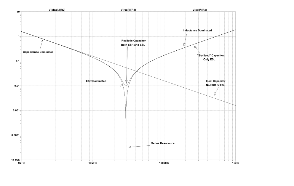
There are also three important features of this graph. The section on the left is where the capacitance value of the cap dominates, where ESL and ESR play no importance in the shape of the line. The section on the right, where inductance (ESL) dominates and the capacitance and ESR play no role. Then there is the central dip where the series resonance created by the capacitance and ESL cause a narrow dip in the impedance.
The series resonance dip always happens where the impedance from the capacitance equals the impedance from the ESL. If there was no ESR, that dip would extend all the way down to zero. But the depth of the dip is actually limited by our ESR.
The caps represented in this graph are 0.1 uF in an 0402 package. The central dip is at about 29 MHz. This is well within the normal operating range of most digital circuits.
The impedance goes above 0.1 ohms at 66 MHz. While not all digital circuits have clocks above that, the harmonics caused by fast signal edges certainly do go above it.
You will also note that the impedance is above 0.1 ohms below 13 MHz. Again, well within the operating range of most circuits.
All of the non-ideal behavior of decoupling caps are in frequencies that affect almost every digital circuit. Being aware of this is extremely important in understanding how to design reliable circuits.
Simulating
Much of decoupling caps behavior is difficult to measure in circuit, so we turn to simulations. Simulating these circuits can make everything easier to understand and is essential for providing insight. The graph, above, was created by a simulation using LTspice. The important features of LTspice is that it very capable and free.
In the Zip file that goes along with this blog post, there is the Simple_Cap simulation. If you can, open that up now. Once open, run the simulation so the plot window pops up. That window should match the graph above.
The first thing worth noting are the formulas at the top of the graph. The formulas are in the form of Voltage/Current. From ohms law we know that Resistance = Voltage / Current. So the vertical scale of the graph is in ohms!
If you right click on the vertical scale on the left of the graph a dialog box will appear. Normally the vertical scale is set to “Decibel”, but I have changed it to Logarithmic. If you right click on the vertical scale on the right side of the graph (the empty space, in this case) you will see options for plotting the phase. I have turned off the phase because it isn’t important here.
Right click on a capacitor and the various parasitic values will be shown, including ESR and ESL. For now, only Capacitance, ESR, and ESL will be used and the others can be ignored.
Each resistor has a 1 pico-ohm resistor in series with it. The only reason for this resistor is to measure current going to the cap— for generating the plots in ohms. There are several other ways to achieve this, but this way makes some things easier. It’s not important here, but will be later.
To properly simulate a cap, you must have the ESR and ESL values to enter into the simulation. In LTspice, you can select a specific manufactures part number for a cap and it will bring in all of that data for that cap. But here is the catch: Most capacitor models do not properly handle ESL and/or ESR!
You might think that the datasheet would contain these values, but you’d be wrong. Kemet even did a write-up on the problem! If you have the impedance graph from the manufacturer then you can use the Simple_Cap simulation to approximate the graph from the manufacturer. Just change the capacitance, ESL, and ESR until it is close.
If you cannot get or approximate the ESL and ESR of the caps then you should not use them in your product. Also, don’t be afraid to complain to the capacitor manufacturer and tell them why you are not using their product. Maybe that would get them to be more cooperative with engineers.
LTspice has the ability to easily simulate multiple caps in parallel. This can be very useful when simulating the affect of a real decoupling cap scenario. I would write about how to do it, but Linear Tech. already did it.
Fanout Inductance
Now that you know about caps, you’ll want to put them on your PCB. The problem with this is that the fanout (cap to trace to via to power/ground plane) has its own inductance that you must factor into account.
Doing an analysis of fanout inductance is beyond the scope of this article. Howard Johnson did a good summary here, with example layouts and the corresponding inductances. The important take away from his write-up is that you want fat and very short traces with vias on the side. The distance between the vias is important. Also very important is the distance from the top (or bottom) layer to the plane that the via connects to.
For simulations, this fanout inductance can be modeled as an inductor in series with the cap, or simply added to the ESL of the cap. I add it to the ESL of the cap because then you can use LT’s trick of modeling multiple caps in parallel and it will then also properly model the fanout inductance too.
Below is the graph of the same 0.1 uF cap, but adding some fanout inductance. I used numbers and terminology from Howard Johnson’s article that I linked to above. You can find this simulation (Via_Comparison) in the same zip file as the other simulations.
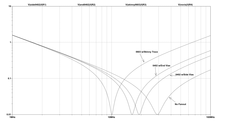
The most obvious effect is that the resonant frequency changed from the original 29 MHz all the way down to 10 MHz. This change will be super important in later blog posts where the resonant frequency becomes a critical design parameter. Another important effect is the impedance above the resonant frequency is significantly higher. Up to 10 times higher! And the last important thing to note is that the resonant dip from each of the caps goes down to the same 0.01 ohms. This is because the ESR is 0.01 ohms and that is the dominating parameter here.
While the ESL of a cap is important, the fanout inductance can be much higher— and that has a huge impact on the effectiveness of our decoupling caps. This is the most important take-away from this article.
Where Others Get It Wrong
I’ve read and watched much content on the ‘net for these series of articles. Originally it was because I didn’t want to explain things that others have already explained in a better way. But most of what I found was so bad, I have a new goal: To warn people about what is bad. Because much of this article was fairly low-level electrical engineering, other blogs and videos get this mostly correct. But there is still room for improvement.
Many people explain capacitors using the stylized version— the version where ESR=0. When ESR is zero, the side effects of series and parallel resonance is much worse. They then go on to make conclusions and generalizations that are not valid.
Other times, people will show the classic impedance graph for a cap but fail to factor in the effects of fanout impedance. Like before, they then go on to make bad conclusions and generalizations.
Conclusion
There is a lot of nuance to capacitors, and much of this nuance is very important to successfully understanding and using decoupling caps. Know your the ESR and ESL of the caps, and know how to simulate them.
The information in this blog post is foundational. If you don’t “get it” then you won’t get any of the follow-up blog posts. Study up on the links I provided above, and ask questions below. And most importantly, experiment with the simulations!