
Ferrite Beads For Filtering Power
You’ve probably seen it before; a ferrite bead and capacitor (LC Filter) used to filter power for specific power pins on an IC. Odds are that you’ve done that yourself. They are frequently used on particularly sensitive parts of a circuit like PLL’s, analog sections, Ethernet transformers, and high speed transceivers.
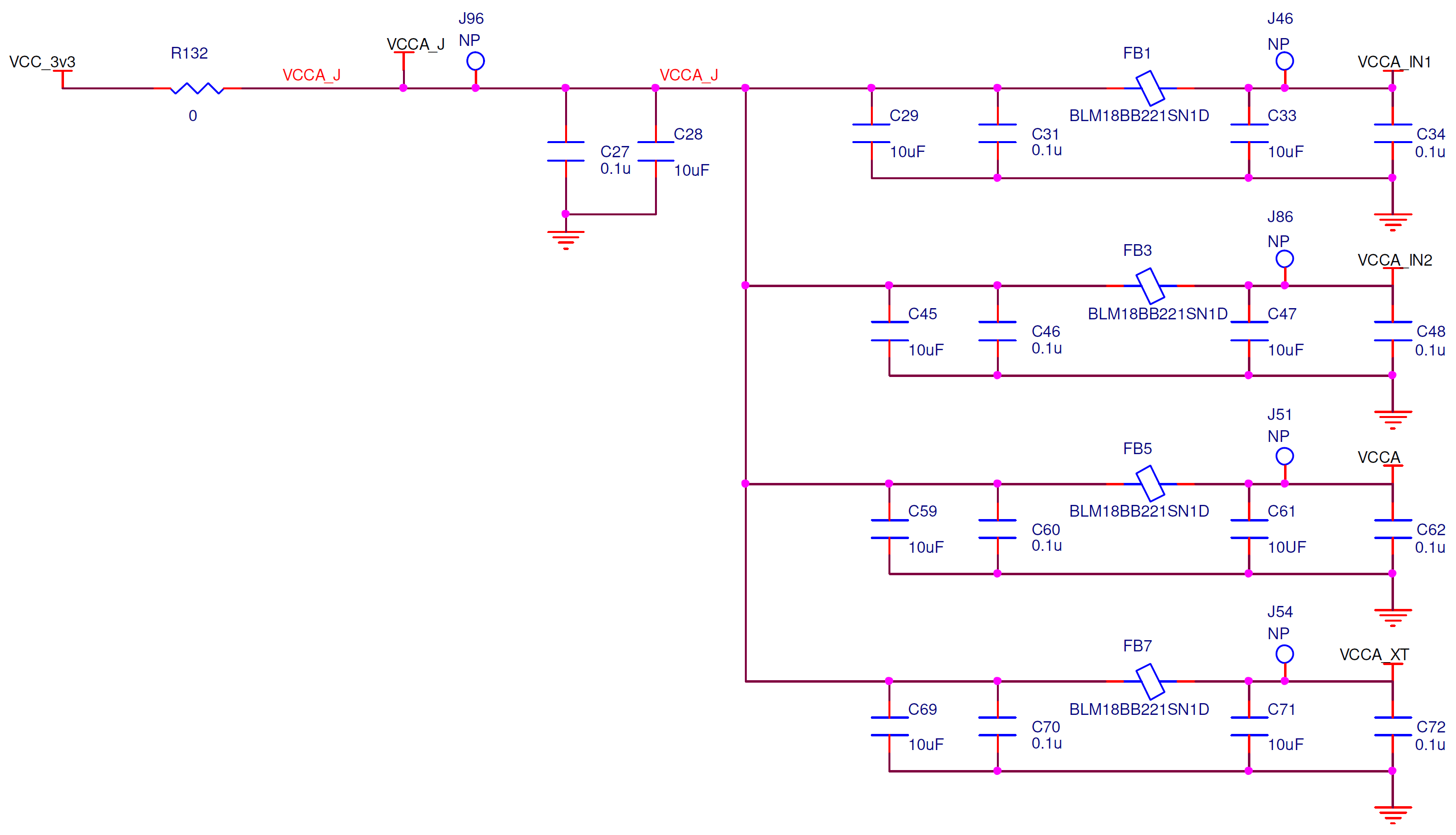
Below is part of an example for powering an IDT clock synthesizer and distribution chip. While it shows LC filters, the total reference design had 12 of these filters!
When you ask engineers why they use these LC filters on power you get wishy-washy answers the are closer to wishful thinking than something they have studied and are confident about.
This article is about designing intentionally. To show you what the real function of these LC filters are, and to give you the knowledge and tools to know if using them is beneficial or a detriment to your circuit.
When it comes to these LC filters, it is all too easy to commit some major logical fallacies: Appeal to tradition and appeal to authority. Using something just because someone else uses them or because it’s always been that way is a dysfunctional habit.
Even if someone really smart used them previously, and they used them correctly, it doesn’t mean that their justification applies to your circuit.
Reasons For Using LC Filters
At its core, LC filters are used to keep noise in one section of the circuit from getting to another section. Sometimes it is noise in the main power section getting into a down-stream quiet section. Other times the noise is downstream and the filter is there to prevent noise from getting into the main power section. For this article, I will assume that we are preventing upstream noise from getting into quiet power downstream— although the same principles apply going to the other direction.
There are three important questions to ask yourself before adding LC filters to your power:
- Should your effort be put into filtering out noise, or preventing noise in the first place?
- Is the noise you are wanting to filtering out actually there?
- Is the LC filter creating more noise than it is removing?
Prevent Or Filter Noise?
Let’s be honest here… If at all possible you want to prevent noise rather than filtering it. There are so many benefits to having lower overall noise, like improved system reliability, improved EMI compliance, and better system operation.
In the previous blog article, Power Integrity and Decoupling Caps, I discussed how to use decoupling capacitors to sculpt a proper power impedance curve for best noise performance. If you followed that article, then your noise on the main power rails should be minimal, and if you still have a noise problem then you have some approaches on how to solve those problems.
Is The Noise Actually There?
This is a hard one to answer, because you often won’t know if you have a noise problem until you build the PCB’s. It is here when your philosophical approach dictates what approach you take. I prefer to prevent the generation of noise rather than filter it out. So I will design my PDN (power distribution network) with that in mind. Assuming I did that correctly then I shouldn’t have much noise, and I can safely assume that I don’t have noise to filter out.
But let’s say that I build the PCB’s and there is noise. Here again, this is where your philosophical approach dictates what you do. My default approach would guide me to fixing the noise generation problem rather than trying to figure out how to filter it out.
Given my default approach, I will not use LC filters on power unless I can prove they are required.
Once you have a PCB to measure, you can deviate from your default approach.
Are LC Filters Actually Helping?
This is where the rubber meets the road. We can divide this up into to questions: Does the LC filter actually filter? And, are there any negative effects from the impedance of the LC filter? Let’s simulate this…
Download the LTspice simulation files here.
Attenuation
The graph below shows how much attenuation we get from a ferrite bead with different selections of caps. This is a measure of how well the filter blocks noise from getting through.
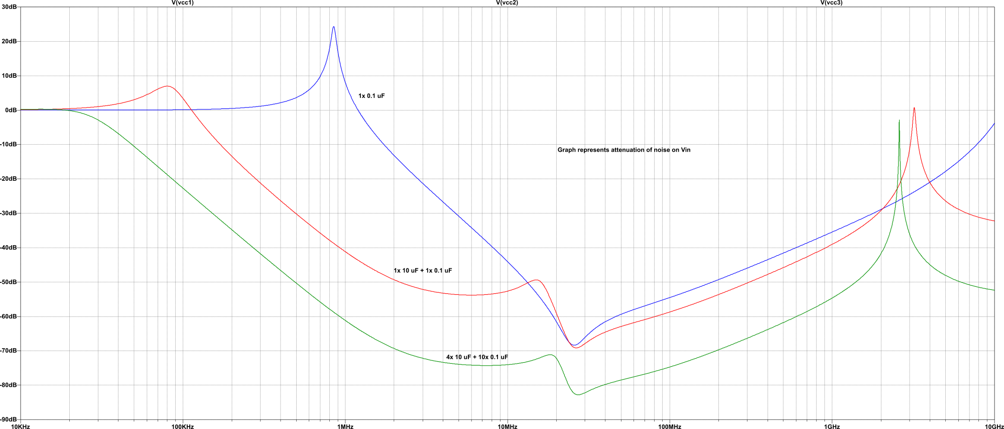
It does a reasonable job, but there are some surprising spikes. With a single cap at 850 KHz there is a +24 dB spike. For those that are not used to reading a dB scale, what is happening here is that we are doing the opposite of filtering. We are amplifying the noise around that frequency by a huge amount. This is due to some resonances between the ferrite bead and our capacitor. For those not familiar with the dB scale, +24db gain will increase the noise in that frequency band by almost 16 times!
If we add a 10 uF cap in addition to our 0.1 uF cap then that resonant peak reduces in amplitude and frequency. There is still a +7 dB bump at 80 KHz, but it depends on your application if that is a problem. We also see a significant improvement in the 100 KHz – 10 MHz range as well. And finally, there is another resonant peak at about 3 GHz.
Going to four 10 uF caps and ten 0.1 uF caps we get the expected improvement, but at significant parts increase.
The resonant peaks at about 3 GHz are worth talking about. It is difficult to know just how real those peaks are. Many simulation models break down somewhere above 1 GHz. The simulator itself is probably fine, but the models used may not be accurate at those frequencies. Additionally, parasitic effects can dominate at those frequencies so nuances of PCB layout (which can be difficult to capture in simple simulations) can affect those peaks greatly. There is a third peak on the 0.1uF only graph, but it is above 10 GHz and isn’t shown here.
From an attenuation standpoint, we can conclude that a single 0.1 uF cap is not sufficient for most applications. Using 10 uF + 0.1 uF seems reasonable. And using 14 caps is better, but overkill.
PDN Impedance
We learned in Power Integrity and Decoupling Caps that the impedance of our power distribution network has a direct impact on noise. Essentially, the lower the impedance (but not too low) the less noise will be generated by the load during transients.
The graph below shows the power supply impedance as seen by the load. The three lines represent a single 0.1 uF cap, a 10 uF plus 0.1 uF cap, and no filter at all. You might recognize the baseline (no filter) as being the PDN from Power Integrity and Decoupling Caps.
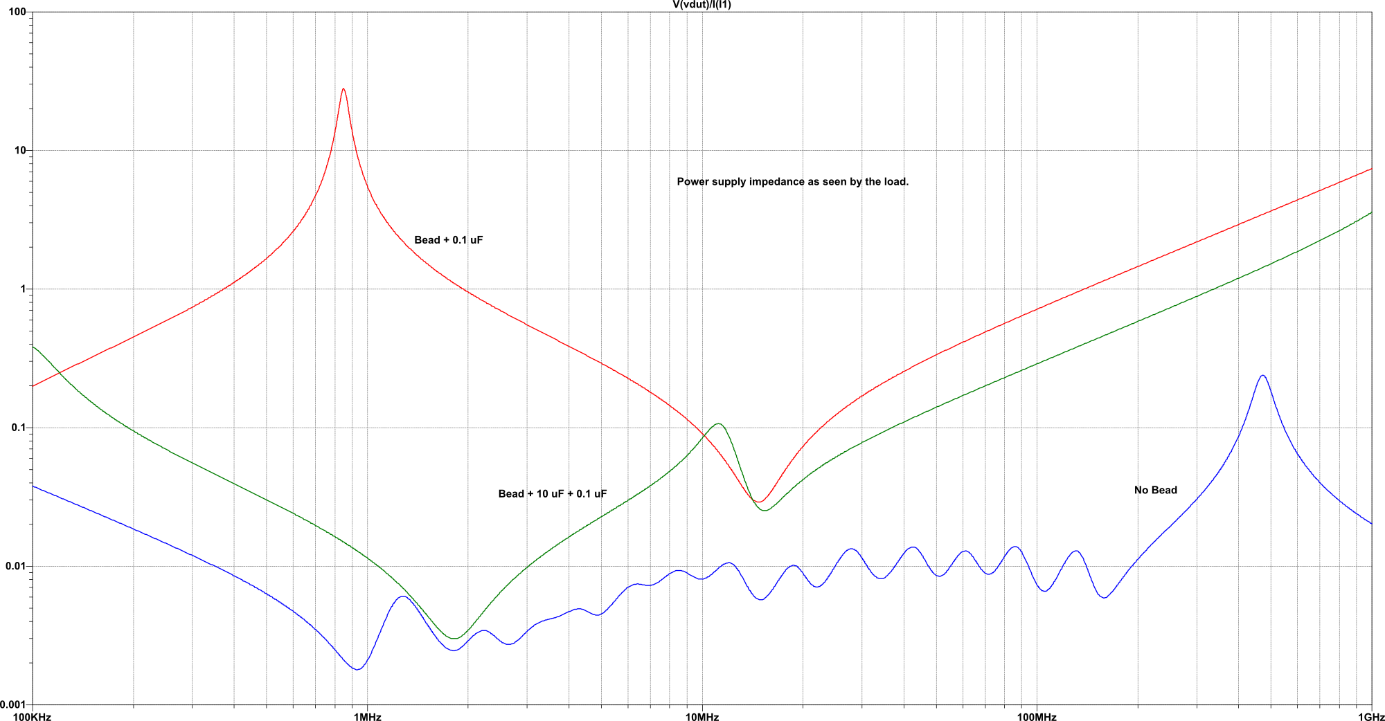
Our goal is to have the PDN impedance to be low enough that the transient load doesn’t cause too much of a voltage drop on the power rail. Using a bead and a single 0.1 uF cap has approximately (just eyeballing it) 3 to 3,000 times the impedance as no bead at all! Adding a 10 uF cap improves things, but it is still 10 to 100 times worse in the higher frequencies.
These impedance graphs are fairly horrible. Anything powered through such an LC filter will certainly generate more noise on the power rail than if the bead was not used. Sometimes 3000 times more noise!
The Pro’s and Con’s Of Using A Filter
Pro’s: Isolates power supply noise to certain parts of the circuit.
Con’s: Can cause more noise than if not using the filter. As much as 100 times more noise! Can mask the more serious problem of noise on your power rails.
The Pro’s and Con’s Of No Filter
Pro’s: Assures that the least amount of noise will be generated (assuming that your main PDN was designed correctly).
Con’s: Least amount of noise generated might still be too much.
Opinion Time
As with everything, the proper way to do it depends on a lot of factors. What does your PDN impedance look like? What kind of transients will your load have? What is the maximum allowable noise on the power rail? These are all difficult questions, and all of them have important implications on what the correct thing to do is.
It is my opinion that we should design a proper PDN and not use LC filters on power. Only then, if it has been proven that there is still too much noise, and all efforts to reduce that noise have failed, should LC filters on power be considered. With this approach, you will be guaranteed to have the lowest noise system possible. This approach should also minimize (over the long-term average) total development time.
The reason why I say this is an opinion is because it is an over-generalization based on experience, and not an established fact. The correct approach would be to simulate the whole thing, including the load-induced transients, but that is often not practical or even possible.